Connecting the JimStim to the MicroSquirt
Recommended Connections
The recommended wiring connections between the MicroSquirt and the JimStim are shown in the table below. The Ampseal connector pin number and pin names correspond to the schematics found here. The function column corresponds to the name given in the table found here. The third column gives the JimStim screw terminal label found on the board itself. N/C indicates there is no connection.
| AmpSeal Connector Pin # (Pin Name) | MicroSquirt Function | JimStim Screw Terminal |
|---|---|---|
| 1 (V12_RAW) | 12 Volt Supply | 12V |
| 2 (CANH) | CAN High | N/C |
| 3 (CANL) | CAN Low | N/C |
| 4 (VR2IN+) | VRIN2+ | SPR1 1,2 |
| 5 | N/C | N/C |
| 6 (FLEX) | Flex Fuel | SPR3 1,3 |
| 7 (IDL) | FIDLE | FIDL |
| 8 (FP) | FUEL PUMP | FP |
| 9 (INJ-1) | INJECTOR 1 | INJ1 |
| 10 (INJ-2) | INJECTOR 2 | INJ2 |
| 11 (IGNOUT2) | IGNITION OUTPUT #2 | I1A 1,4 |
| 12 (IGNOUT) | IGNITION OUTPUT #1 | IGN 4 |
| 13 (RXOUT) | SERIAL Rx | N/C |
| 14 (TXOUT) | SERIAL Tx | N/C |
| 15 (BOOTLOAD) | BOOTLOADER | N/C |
| 16 (ALED) | ACCEL LED | I2A 1,4 |
| 17 (WLED) | WARM-UP LED | I2B 1,4 |
| 18 (GROUND) | N/C (ground) | Ground 6 |
| 19 (GROUND) | SERIAL GROUND | N/C |
| 20 (GROUND) | SENSOR GROUND | Ground 6 |
| 21 (GROUND) | GROUND | Ground 6 |
| 22 (GROUND) | GROUND | Ground 6 |
| 23 (GROUND) | GROUND | Ground 6 |
| 24 (MAP) | MAP | SPR2 1,3 |
| 25 (CLT) | CLT | CLT |
| 26 (MAT) | IAT | MAT |
| 27 (TPS) | TPS | TPS |
| 28 (Vref) | Vref | 5V |
| 29 (SPAREADC) | SPARE ADC | SPR4 1,3 |
| 30 (OPTOIN+) | OPTOIN+ | TACH 5 |
| 31 (OPTOIN-) | OPTOIN- | Ground 6 |
| 32 (VRIN+) | VRIN+ | TACH 5 |
| 33 (VRIN-) | VRIN- | Ground 6 |
| 34 (O2) | O2 | O2 |
| 35 (TACHOUT) | TACH OUTPUT | I1B 1,7 |
1 : These are spare pins on the JimStim (and the MegaSquirt V3.0 board) which are reused for other MicroSquirt functions.
2 : The corresponding pin on the JimStim 19-pin header needs to be connected to the 2nd trigger header pin to use this function. See this.
3 : These analog signals can be simulated one at a time using the JimStim spare ADC potentiometer. Connect the corresponding 19-pin header pin to the spare ADC header pin. See this.
4 : These output signals can be viewed using the JimStim ignition LEDs. Connect the corresponding 19-pin header pin to the LED header. Ignition output #1 can be connected to the first LED header pin, ignition output #2 to the second pin, the accel LED to the third pin, and the warm-up LED to the fourth pin. See this.
5 : The JimStim primary tach signal can be connected to either one of these (one at a time). Configure the JimStim accordingly. See this.
6 : The Microsquirt ground can be connected to the JimStim ground using the ground header.
7 : The tach output signal can be viewed using the JimStim IAC LED. Connect the I1B pin on the 19-pin header to the next to last LED header pin and connect the last pin of the LED header to ground. See this.
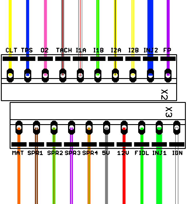
The picture below shows the JimStim screw terminals with the wire color corresponding to the MicroSquirt harness wire color(s) (main/stripe). The Tach input as shown is for the OPTOIN option. To use the VRIN option use the coax wire instead of the gray/red wire. The ground wires are connected to the JimStim ground header.
Note: The bigger green wire goes to the INJ1 screw terminal and the smaller green wire goes to the FIDL screw terminal. The bigger blue wire goes to the INJ2 screw terminal and the smaller blue wire goes to the TPS screw terminal.
