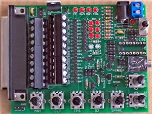
JimStim v1.1 Assembly Instructions
Assembly
- Install and solder R1 to R10 (330Ω).
- Install and solder R11, R12, R20, R21, R22, R24, R25 (1KΩ), R26 (4.7KΩ), R27 (39KΩ). Please note that R26 is positioned differently on the V1.1 board than on the V1.0 board pictured below.
- Install and solder D1 (1N4004 diode). Make sure that the banded side is towards the DB37.
- Install and solder C1 (10µF) and C2 (0.22µF). As opposed as what is shown in the picture below, C1 is blue and not yellow if you have purchase the one from the BOM.
- Install and solder Q1 and Q2. To install them you will have to bend the middle lead 90 degrees back and the another 90 degrees down as shown here:

Each straight section is about 1/8 inch. - Install and solder the processor socket.
- Install and solder the 11 red LEDs and the 2 bicolor LEDs. All short leads must be on the left when looking at the picture below (DB37 side).
- Install the audio jack besides the processor socket. Install and solder the power jack (X5). Install and solder U2 (voltage regulator). The metal tab is facing outside the board.
- Break away the single row pin header to have: 1 19-pin section, 1 10-pin section, 3 3-pin sections, 1 2-pin section, and 4 individual pins. Break away the dual row pin header to have: 1 6x2 section, 2 3x2 section, and 1 2x2 section. Install and solder all the pin header sections. Please note that the 3x2 BDM header is positioned differently on the V1.1 board than on the V1.0 pictured below.
- Install and solder the DB37 connector.
- Install and solder the 2-position terminal block (X4). Install and solder the toggle switch (S1).
- Install and solder the 7 potentiometers.
- Install and solder the 2 10-position terminal blocks (X2 and X3).
Making the JimStim ready for use
The final step is to install the processor in the socket.
This completes the assembly of the JimStim. To use the stim, power must be applied to either the power jack or the 2-position terminal block. To send a tach signal to the Megasquirt board, a wire jumper must be installed between the 1-pin primary tach header and the tach pin on the 19-pin header. The terminal block can be used instead of the 19-pin header. Alternatively, a wire can be soldered between those 2 points but this makes it a permanent connection.
